
Annotation
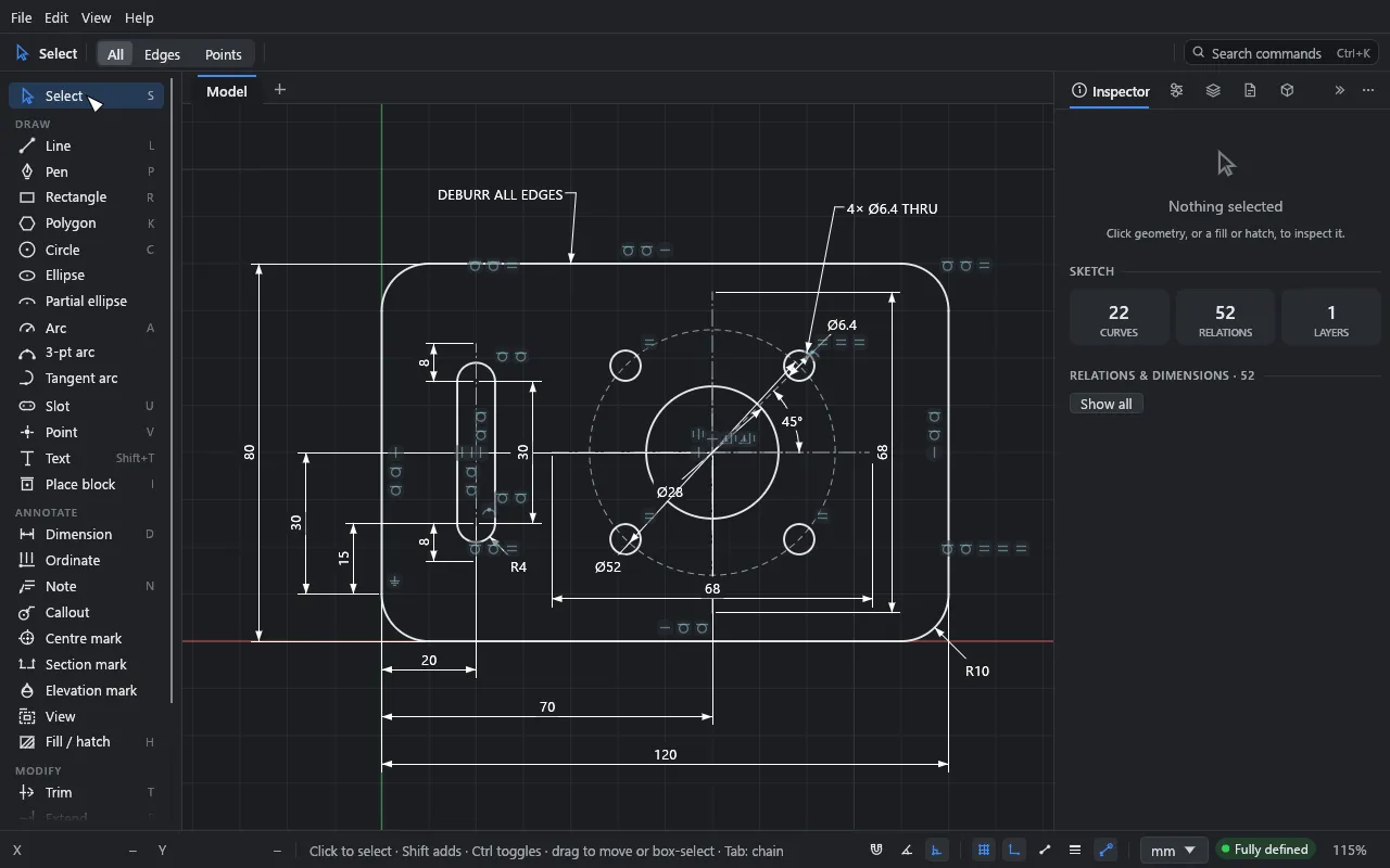
What you’ll make: the example plate, annotated for the workshop: a note with a leader, a centre mark, a hole callout, section and elevation marks, and a dimension marked TYP. Then you’ll hide some annotations on the canvas or leave them off the sheets.
Time: about 15 minutes.
Open the example (File → Open example). The annotation tools are in the Annotate group of the tool palette.
1. A note with a leader
- Press N for the Note tool.
- Click the plate’s top edge. That’s where the leader’s arrow goes.
- Click above the plate, where the text goes.
- Type
DEBURR ALL EDGESand press Enter. (Shift+Enter starts a new line; Esc cancels.)
For a note without a leader, click empty canvas in step 2 and go straight to typing. For several leaders, Shift+click more geometry after the first, then click where the text goes.
Leaders attach to points, or anywhere along a line or curve, so they follow the geometry when it moves.
More leaders, and changing them
Pick a note with Select and it shows grips:
- + on either side of the text: drag from one to anything to add a leader there.
- A square at each leader’s end: drag it to attach the leader somewhere else.
- A circle at a bent leader’s bend, or at a curved leader’s middle: drag it to move the bend, or to bow the curve further, less, or the other way.
- A diamond where a leader meets its shoulder: drag it along the text’s line to lengthen or shorten the shoulder (all the way in turns the shoulder off).
Click a leader’s line to pick just that leader, and press Delete to remove it. The text stays where it is. Add leader in the Inspector does the same as a +: click it, then click what the leader points to.
The Inspector lists the note’s leaders. For each:
- End: Arrow, Open arrow, Dot or None.
- Shape: Straight, Bent (through a bend you can drag), or Curved (drag its middle to bow it).
- Shoulder: a short level line into the text, as on Revit and SolidWorks notes; its length is set on the canvas.
- × removes it.
The text
The Inspector’s Style section sets the note’s text: a Size of its own (or the drafting style’s), Bold and Italic, Align (left, centre or right), Wrap to a width, a Frame (a box or a rounded box) and Mask what’s behind it, which puts paper behind the text so it reads over hatches and lines. Double-click a note to edit its text.
2. A centre mark
- Click Centre mark in the tool palette.
- Click the bore.
Click another circle, arc or point next, and you get a centre line through both centres. Click two lines to get a centre line midway between them. Esc stops.
To mark several circles at once, pick them with Select and click Add centre marks in the Inspector.
3. A hole callout
- Click Callout in the tool palette.
- Click one of the bolt holes.
- Click where the text goes.
Drift counts the holes of the same size: the callout reads 4× Ø6.4 THRU. Pick it to
change the suffix to TAP, CBORE or CSK. Click a chamfer’s line instead to get
2 × 45° (or 2 × 3 for unequal legs).
4. Ordinate dimensions
- Click Ordinate in the tool palette.
- Click the point to measure from. It reads 0.
- Click more points. Each gets its X distance from the origin point, lined up in a row.
- Press Y to measure Y distances instead (X to go back). Esc finishes.
5. Section and elevation marks
- Click Section mark, then click where the cutting line starts and where it ends. Press X or Y before the second click to keep it along an axis. Each end gets a flag with the next free letter (A, then B…).
- Click Elevation mark, click where the mark goes, then click towards what it looks at. X and Y keep it to an axis; Alt allows any angle. It gets the next free number.
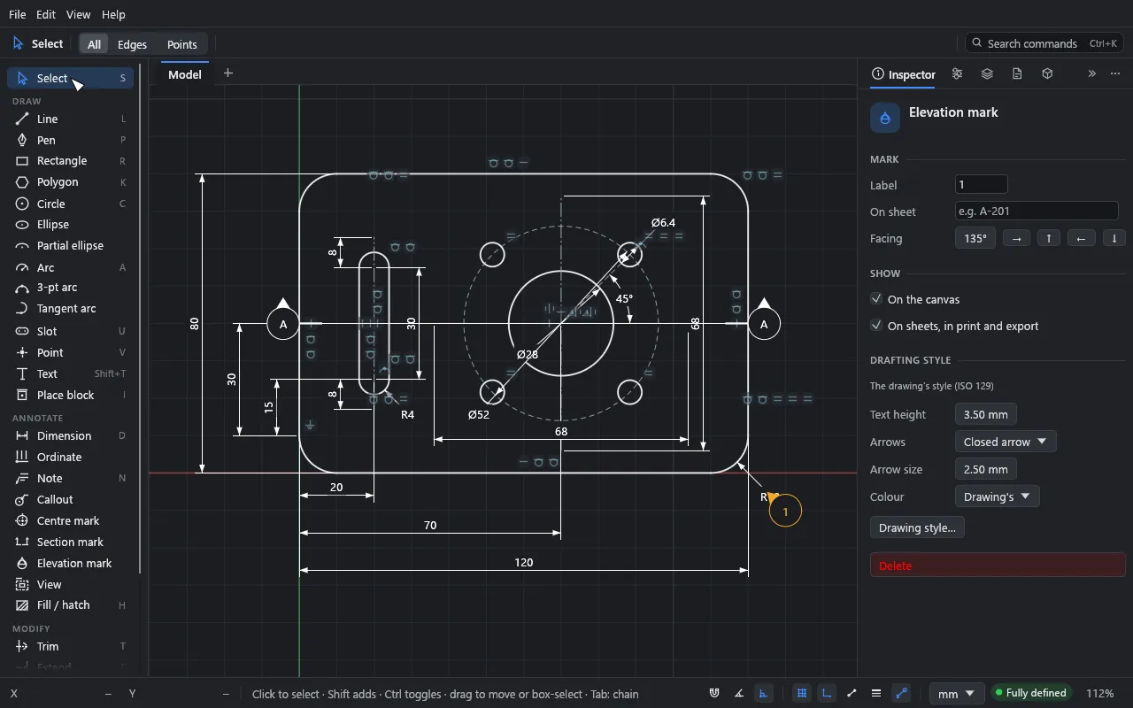
Pick a mark to edit it in the Inspector: its Label, On sheet (the sheet it’s
drawn on, shown in the lower half of the flag, such as A-201), and which way it looks
(a section’s Direction has Flip, to look the other way, and Swap ends; an
elevation’s Facing has an angle and →, ↑, ←, ↓ buttons). Drag a mark to move it whole.
Marks linked to views
A mark can point at a view of the model, the way a Revit section points at its section
view. Its flag then reads the view’s number over the number of the sheet it’s on, such as
2 / A-501, and keeps up by itself: renumber the sheet or move the view and the flag
follows.
- Right-click a mark → Make view makes a view of what it looks at, named after the mark (Section A, Elevation 1) and linked to it. A section’s view runs along its cutting line, as deep as the drawing goes the way it looks; an elevation’s takes in what is in front of it. It gets the largest standard scale at which it fits 180 × 120 mm of paper. The view is picked in the Views list of the Sheets panel, ready to place on a sheet (see Sheets and output). One undo takes it all back.
- In the mark’s Inspector, View links it to any view, or to None. While it’s linked, Reads shows what the flag says, in place of On sheet.
- Until the view is placed on a sheet the flag reads
– / –. Delete the view and the mark goes back to its own label and sheet.
6. Dimension text
Double-click a dimension’s value. Under the value field are:
- before and after fields, for text either side of the value.
- Chips that toggle common text on and off: ×, Ø, ±, TYP, REF, MIN, MAX, VIF, THRU and EQ.
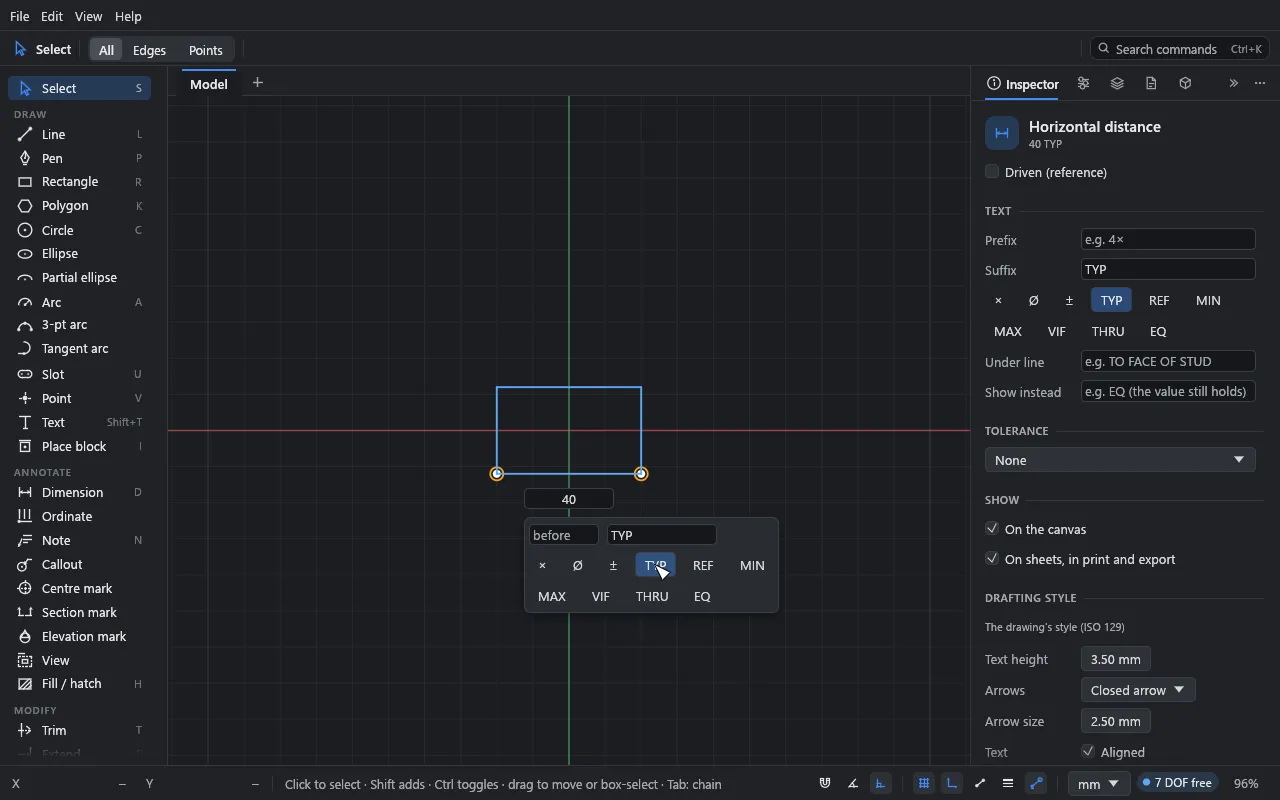
Pick a dimension (click its value once) for more in the Inspector:
- Prefix and Suffix, and the same chips.
- Under line: a second line of text under the dimension line, such as
TO FACE OF STUD. - Show instead: text shown in place of the value, such as
EQ. The dimension still holds its value; only the text changes. (Tolerances and dual units aren’t shown with it.) - Tolerance: None, Symmetric (±), Deviation (stacked + and −), Limits
(stacked) or Fit (such as
H7). - Driven (reference), as in Constraints and dimensions.
7. Hide annotations, on the canvas or on sheets
Every dimension and annotation has two switches, in the Inspector’s Show section:
- On the canvas. Turned off, it isn’t drawn and can’t be picked. A hidden dimension still holds its value.
- On sheets, in print and export. Turned off, it stays on the canvas (marked with a struck-through sheet badge) but is left out of sheets, PDF, SVG, DXF and printing.
Once the drawing has views (see Sheets and output), In views says which of them it’s drawn in on sheets: All views (the default, which includes views you make later), or only the ones you tick. A note meant for the detail alone, say, then stays out of the plan. It’s always on the canvas. If you delete the only view it was in, it’s left off sheets rather than appearing everywhere.
Shift+click picks several dimensions and notes to change at once. The right-click menu has Hide on canvas and Leave off sheets too.
To bring hidden ones back, press Alt+H (or View → Hidden annotations, or click the N hidden pill in the status bar). Hidden annotations then show faded, so you can pick them and switch them back on. Alt+H again hides them.
Alt+D hides or shows every dimension and note at once (View → Dimensions and notes). That’s a view setting; it doesn’t change the drawing.
The drafting style
The look of dimensions and notes is set for the whole drawing in File → Drawing settings… → Drafting:
- ISO 129 or ASME Y14.5. ISO writes text aligned above the dimension line; ASME writes it horizontal, in a break in the line.
- Text height, Arrows (closed, open, tick, dot) and Arrow size, extension line gap and overshoot (Ext. gap, Ext. past), leading and trailing Zeros, and Dual units.
- Colour on the canvas (paper output isn’t affected), and a Font for all annotation and title-block text. A font you pick is kept inside the drawing, where its licence allows, so it looks the same on another computer and in PDFs.
Sizes are paper sizes: text set 3.5 mm high prints 3.5 mm high, whatever the sheet’s scale.
One dimension or note in its own style
Pick a dimension (or several, or a callout, mark or note) and open the Inspector’s Drafting style section. Each row shows what it is drawn with. Change one, say Arrows to Tick for a detail, and that setting becomes the object’s own: its label turns blue and a reset arrow appears beside it. Everything you leave alone keeps following the drawing, so a later change to the drawing’s style still reaches it.
- The reset arrow puts one setting back to the drawing’s; Reset all puts them all back.
- Text height, arrows and arrow size, aligned text, zeros, dual units and colour can be overridden. The standard and the scale belong to the drawing.
- A note keeps its own text size in its Style section, as before.
- Drawing style… at the foot of the section opens the drawing’s settings.
What you learned
- N places notes (with a leader if you start on geometry); Callout, Centre mark, Ordinate, Section mark and Elevation mark are in the Annotate group.
- Double-click a dimension for before / after text and chips like TYP and EQ.
- Each annotation can be off the canvas or off the sheets; Alt+H shows hidden ones.
- The drafting style is the drawing’s (File → Drawing settings…); a picked dimension or note can override any of it for itself, with a reset arrow to go back.